With the availability of a density source, the next step now is to construct triangles out of it. The classic approach is Marching Cubes by Lorensen and Cline [LC87]. Instead of giving a lot of formulas like before, this article mainly shows code.
The name can be taken literally, cubes are marching over a grid. In figure 1 is the indexing of the corners of a single.

1: Corner indices of a cube
The march is done in a big three dimensional loop. The start and end variables as well as the cube width is set before.
for (Real z = zStart; z <= zEnd; z += cubeWidth)
{
    for (Real y = yStart; y <= yEnd; y += cubeWidth)
    {
        for (Real x = xStart; x <= xEnd; x += cubeWidth)
        {
            Vector3 corners[8] =
            {
                Vector3(x, y, z),
                Vector3(x + cubeWidth, y, z),
                Vector3(x + cubeWidth, y, z + cubeWidth),
                Vector3(x, y, z + cubeWidth),
                Vector3(x, y + cubeWidth, z),
                Vector3(x + cubeWidth, y + cubeWidth, z),
                Vector3(x + cubeWidth, y + cubeWidth, z + cubeWidth),
                Vector3(x, y + cubeWidth, z + cubeWidth),
            };
            Vector4 values[8] = {
                source->getValueAndGradient(corners[0]),
                source->getValueAndGradient(corners[1]),
                source->getValueAndGradient(corners[2]),
                source->getValueAndGradient(corners[3]),
                source->getValueAndGradient(corners[4]),
                source->getValueAndGradient(corners[5]),
                source->getValueAndGradient(corners[6]),
                source->getValueAndGradient(corners[7])
            };
            handleCube(corners, values);
        }
    }
}
As you can see, each cube is defined by it’s corners, their density values and their gradient. And each cube is handled independently. First, a index is build by inspecting each cube corner whether it’s inside or outside of the volume, ISO_LEVEL is normally 0:
for (size_t i = 0; i < 8; ++i)
{
    if (values[i].w >= ISO_LEVEL)
    {
        cubeIndex |= 1 << i;
    }
}
A big edge table with all 256 possibilities saves the volume intersecting edges for each index:
int edge = mcEdges[cubeIndex];
There are 256 possibilities because each corner of the cube can be either inside or outside of the volume, 
With this edge variable, the intersecting edges of the cube are known. So somewhere between the two corners of the specific edge, the density must be 0 and so the surface is found. The first edge for example is between corner 0 and 1. All in all, a cube has twelve edges which needs to be handled.
Vector3 intersectionPoints[12];
Vector3 intersectionNormals[12];
if (edge & 1)
{
 intersectionPoints[0] = interpolate(corners[0], corners[1], values[0], values[1], intersectionNormals[0]);
}
if (edge & 2)
{
 intersectionPoints[1] = interpolate(corners[1], corners[2], values[1], values[2], intersectionNormals[1]);
}
if (edge & 4)
{
 intersectionPoints[2] = interpolate(corners[2], corners[3], values[2], values[3], intersectionNormals[2]);
}
if (edge & 8)
{
 intersectionPoints[3] = interpolate(corners[3], corners[0], values[3], values[0], intersectionNormals[3]);
}
if (edge & 16)
{
 intersectionPoints[4] = interpolate(corners[4], corners[5], values[4], values[5], intersectionNormals[4]);
}
if (edge & 32)
{
 intersectionPoints[5] = interpolate(corners[5], corners[6], values[5], values[6], intersectionNormals[5]);
}
if (edge & 64)
{
 intersectionPoints[6] = interpolate(corners[6], corners[7], values[6], values[7], intersectionNormals[6]);
}
if (edge & 128)
{
 intersectionPoints[7] = interpolate(corners[7], corners[4], values[7], values[4], intersectionNormals[7]);
}
if (edge & 256)
{
 intersectionPoints[8] = interpolate(corners[0], corners[4], values[0], values[4], intersectionNormals[8]);
}
if (edge & 512)
{
 intersectionPoints[9] = interpolate(corners[1], corners[5], values[1], values[5], intersectionNormals[9]);
}
if (edge & 1024)
{
 intersectionPoints[10] = interpolate(corners[2], corners[6], values[2], values[6], intersectionNormals[10]);
}
if (edge & 2048)
{
 intersectionPoints[11] = interpolate(corners[3], corners[7], values[3], values[7], intersectionNormals[11]);
}
Interpolate returns the exact point on the surface and stores it’s normal in the intersectionNormals array. It handles some edge cases where the isosurface is exactly on one of the two cube corners. If not, it’s just a linear interpolation based on the density values on the edge corners.
Vector3 interpolate(const Vector3 &v0, const Vector3 &v1, const Vector4 val0, const Vector4 val1, Vector3 &normal) const
{
    if (fabs(val0.w - ISO_LEVEL) <= FLT_EPSILON)
    {
        normal.x = val1.x;
        normal.y = val1.y;
        normal.z = val1.z;
        return v0;
    }
    if (fabs(val1.w - ISO_LEVEL) <= FLT_EPSILON)
    {
        normal.x = val1.x;
        normal.y = val1.y;
        normal.z = val1.z;
        return v1;
    }
    if (fabs(val1.w - val0.w) <= FLT_EPSILON)
    {
        normal.x = val0.x;
        normal.y = val0.y;
        normal.z = val0.z;
        return v0;
    }
    Real mu = (ISO_LEVEL - val0.w) / (val1.w - val0.w);
    Vector4 normal4 = val0 + mu * (val1 - val0);
    normal.x = normal4.x;
    normal.y = normal4.y;
    normal.z = normal4.z;
    normal.normalise();
    return v0 + mu * (v1 - v0);
}
For each possible cube of the 256 configurations, another table holds the actual triangulation. Have a look at figure 2 for an example triangulation where three corners are inside of the volume and five edges intersecting.
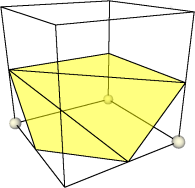
2: Triangulation of a cube configuration
The table mcTriangles stores 256 arrays having 16 integers. As a cube can have a maximum of five triangles with three indices each, we need up to 15 integers. The last triangle is marked with the index -1, so with the maximum amount, element 16 of the cube configuration array is always -1. A triangle consists out of the interpolated three positions and the according normals.
for (int i = 0; mcTriangles[cubeIndex][i] != -1; i += 3)
{
    addTriangle(intersectionPoints[mcTriangles[cubeIndex][i]], intersectionNormals[mcTriangles[cubeIndex][i]],
        intersectionPoints[mcTriangles[cubeIndex][i + 1]], intersectionNormals[mcTriangles[cubeIndex][i + 1]],
        intersectionPoints[mcTriangles[cubeIndex][i + 2]], intersectionNormals[mcTriangles[cubeIndex][i + 2]]);
}
You might have noticed, that in the original paper, the authors boil down the 256 possible cube configurations down to 15 cases, using inverted and rotated symmetries. But this leads to a problem with so called diagonal configurations of two adjacent cubes. A diagonal configuration is always the case when the in and out corners are configured on a side like this:
0 1
1 0
or
1 0
0 1
If the symmetry of negation is used, those cases can’t be distinguished anymore. A negation symmetry means that the in/out markings of the corners are inverted and the same triangulation is taken. You need just one triangle in both cases: Either just one corner is inside of the volume or seven are. Because of the mentioned ambiguity, holes in the mesh can appear. Look at figure 3 for an example. On the left side, the triangulation of a single cube look right, but if you stick both together, holes appear. The correct triangulation is shown on the right.
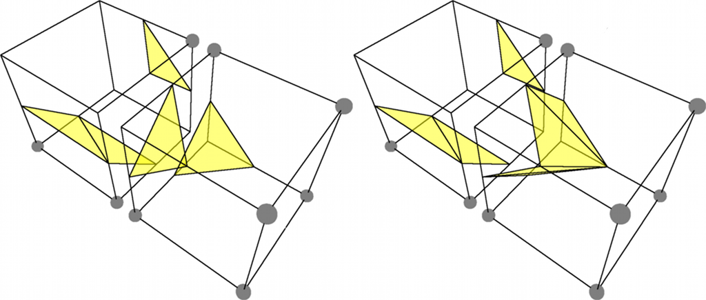
3: Ambigious cases leading to holes in the Marching Cubes mesh
It was Nielson who discovered that this can be easily fixed by just leaving out the negation symmetry and this is why in this implementation, the tables mcEdges and mcTriangles have all 256 elements [Nie03, P. 9]. You find them in the source of OGREs volume component in the file OgreVolumeIsoSurfaceTablesMC.h.
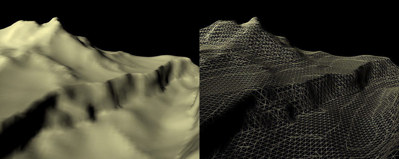
4: Terrain rendered with Marching Cubes
Here is the result of Marching Cubes with a white, lit material.
The high amount of triangles is obvious, even in flat areas where they are not needed. This is due to the nature of Marching Cubes where the cubes don’t vary in size. This problem is covered in a later article. But with this, you are able to basically create meshes from any density source.